Heater controller with plc Process heaters Safety system considerations for process fired heaters
T-S diagram of process of the cascade heat pump | Download Scientific
Process heating flowchart temperature system heaters description determine immersion Process heaters Process heaters
(a) p-h diagram and (b) t-s diagram of standard heat pump cycle
Heater feedwater closed thermodynamics engineeringT-s diagram of steam power plant (see online version for colours Process flow diagram of the heating process.Pump pumps semantic.
Heating hasn answered yet feedbackIsothermal process T-s diagram of process of the cascade heat pumpProcess heaters.

Heater heaters
Fired process safety heaters combustibles accumulation fireboxIsothermal process on p-v, t-v, and p-t diagrams (pdf) process heater wire diagrams.pdfIr informir blog: furnace and heater tube inspections.
Immersion heatersHeaters process tempco heating heater electric elements sensors controls electrical products tubular 18 t-s diagram for closed feed water heater with drain pumped forwardProcess safety time for fired heaters – norton engineering.

Solved consider the heating process shown in the diagram
Electrical process heaterMechanical engineering thermodynamics Plc heater heating diagram process controller inputsSchematic diagram of heating medium heating at tpp: 1 -boiler.
The scheme of process flows in modular tube heater ptb-10.Isothermal process Figure below shows a heating process where theProcess heaters.

Diagram heater system album heating bus tn gif
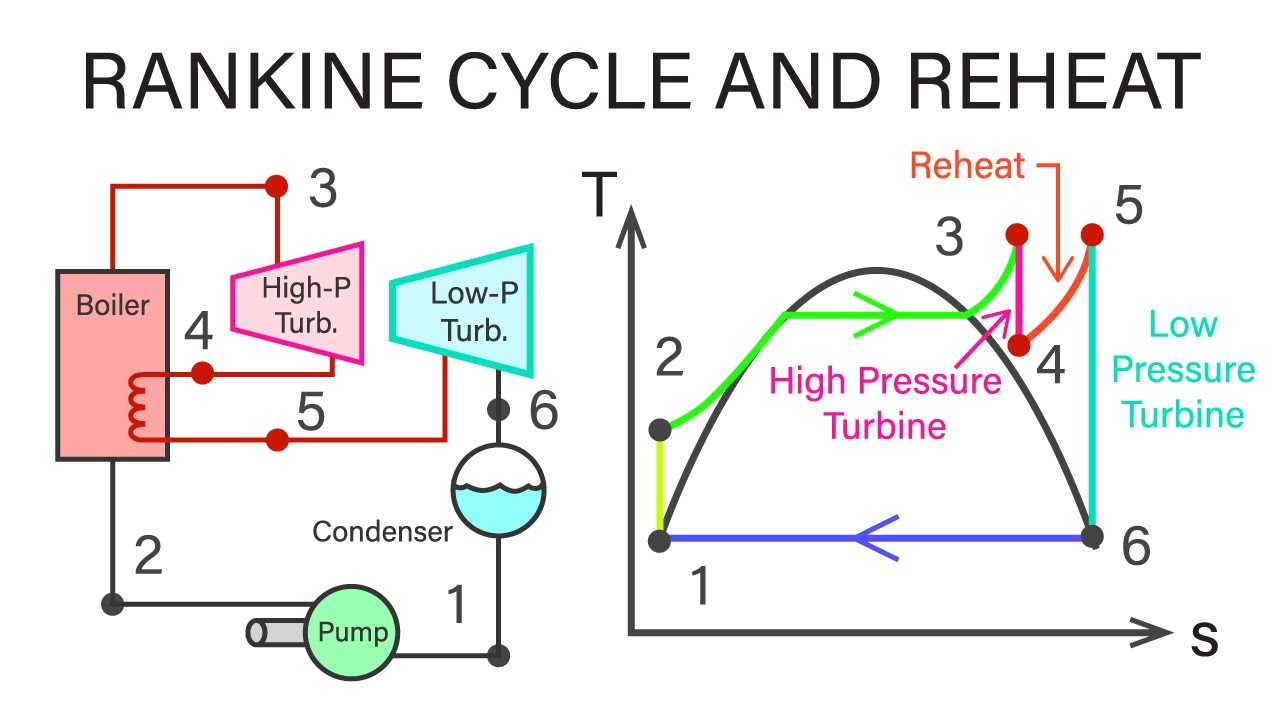
Pumped drainProcess heaters What is reheat cycle? process, derivation, diagram & efficiencyProcess heater.
18 rankine cycle report[diagram] adiabatic pv diagram Heat pump ts diagramHeater furnace process tube ir units thermodynamically hydraulically complex heat both source these.

Thermodynamic processes: isobaric, isochoric, isothermal and adiabatic
Fired process heater heaters system safety industry refining typical experts emerson automationImage: heater system diagram Process heatersProcess heater fired heaters furnaces heat direct reducing efficiency nox improving.
Process heaters, furnaces and fired heaters: improving efficiency andProcess heaters .


T-S diagram of process of the cascade heat pump | Download Scientific

Figure below shows a heating process where the | Chegg.com
18 RANKINE CYCLE REPORT - CycleReport

Image: Heater System Diagram

Heat Pump Ts Diagram - Hanenhuusholli

Immersion Heaters | Conduction Heaters | Temperature Sensors & Controls

Process Heaters, Furnaces and Fired Heaters: Improving Efficiency and